I managed not to break, burn or otherwise ruin anything today. And for that reason I say it was a good day.
Having learned how to connect the off delay relay to the system, thanks to the selfless sacrifice of the original relay, I was able to finish all the wiring for the multiple switches and relays that will power the power steering pump. When the replacement relay arrives, I simply have to drop it into the socket that I already have wired and fastened to the car.
I finished up some other wiring as well; the heater element and all it's switches and relays, the DC to DC converter that will provide 12 volt power to and also isolate the Link 10 battery monitor as well as some miscellaneous little things. There really isn't much more I can do in the way of wiring until the batteries arrive and I can start putting them in place.
One of the things I'd like to try and do is make the car more streamline. People will often cover all the divots and cavities on the undercarriage of the car so there are as few aerodynamic disturbances as possible. The one thing I think I'll easily be able to cover is the area where the transmission sits and the drive shaft back to the differential. It's a long straight cavity about 48 inches in length and there are bolts sticking down on either side at regular intervals. Those bolts held things like heat shielding for the exhaust system and the fuel lines. Now they will make handy anchors to hold the pieces of aluminum that I intend to cover that cavity with. I think tomorrow I'll start measuring and cutting the aluminum sheet I have and see if I can fit in into place.
Saturday, November 28, 2009
A Rough Day In the Garage
Black Friday took on a completely different meaning for me yesterday. While most of this great capitalist nation was out shopping for bargains, I was in the garage experiencing a completely different sort of stress. There were a few other things my day had in common with all the shoppers; it was expensive, and by the end of the day I was frankly too tired to write about it.
Earlier in the week I got the bushing back I'd ordered from the machine shop. You may recall that I need to mount a pulley to the tail shaft of the 11" WaRP motor so that I can run my AC compressor off of it. The bushing is beautifully made, take a look:

It's milled from a solid piece of aluminum, the cylinder is keyed so that it won't spin on the motor shaft, and he even milled a little ridge on the front side that perfectly holds the pulley in place. Very nice work.
So I fit it onto the tail shaft of the motor, and immediately realized I had two problems. In order to get the groves on the pulley to line up with those on the AC compressor, I would need to mount the pulley so far forward that I won't be able to use the motor RPM sensor that I have. I hemmed, hahed and scratched my head for a while, but there is no getting around it. Fortunately, there is a new type of sensor available that should work, but that's another $100 toward the cause. The only thing I've found I hate more than having to build something twice, is having to buy something twice. Very painful.
Turns out that may all be moot, at least for now. I was very careful to build the bracket for the AC compressor so that the pulley was flush with the face of the motor. If it didn't line up right, the belt would come off or simply disintegrate with wear in a short time. As I looked further I realized that while I'd lined it up perfectly on one axis, there was a tilt to the motor that I hadn't matched with the compressor.
Sadly I had to admit that there was no way it would work in it's present state. In reality the only way to make it work was to rebuild the brackets completely. Of course the problem is that getting the alignment right on one axis was hard enough. Getting it right on two will be crazy hard and frustrating. I realized the best, and correct solution is to build the bracket so that it mounts to the face of the motor rather than the chassis. Obviously that will be another custom made machined part. But there's no getting around it, it's the right way to go. Ultimately I decided to shelve that work for now. I want to get the car on the road and the weather is beautiful right now, so the compressor and all it's supporting parts came out. Perhaps in April or so, it can rejoin the rest of the car.
Moving on, I decided to figure out and install the off delay timed relay for the power steering pump. I labored over the electrical diagram for some time trying to coax out the mysteries that it held. After a few dark incantations I was pretty sure that I had it correct, so I hooked it up and tried it. Well, it didn't do quite what I wanted. It came on with power constantly fed through one contact, but never moving to the timed contact. I re-evaluated and decided I'd seen my mistake and tried again. This time it worked! Once.
Apparently, I wasn't supposed to send 12 volts to a particular pin. It managed to trigger the coil once and likely fried it in the process. So, a replacement is on the way to the tune of $27. Not not too much, but frustrating none the less.
From what I learned yesterday, I'll be able to wire everything up so that I can just drop the new relay in place when it arrives. I'm hoping that today will be much more productive and less costly.
Wednesday, November 25, 2009
Odds & Ends Part X
Sorry, another day without pictures. Let's see... What did I do today?
I decided I better sort out that problem with the heater fan. You may remember the story. After soldering a wire to one of the leads coming off the wiring harness on the heater fan switch, I put it all back together. Once I hooked the 12 volt battery up, I found the fan ran at low speed constantly, even when the switch was off. Although it didn't look like it, I must have messed up that harness. I tried like hell to take that harness apart, but it's built better than Scarlett Johansson! Eventually I decided the best way to eliminate the problem was to eliminate the wiring harness I'd fouled up and just hook the individual wires up to the switch directly. A quite simple thing since I could connect them all with normal blade connectors crimped onto the wires.
Once I had all the wires on and the switch on, I hooked the battery up again and... whirrrrrrrr. What!!! I was totally baffled. It was at that point I looked down and happen to gaze upon the switch that turns on air recirculation in the cabin. No way... Yes. I pressed the button and the fan went off. *sigh* At least it works now.
I did lots of other little bits today. I built the wires that will run from the charger to the batteries. Since I was pleased with the LED lights I had, I went ahead and installed the rest. They really do look great. I tested that other LED head light as well and found it to be crap just like the first. That's too bad, I'd really hoped they'd be good. I spent some time gathering up and running wires in bunches and anchoring them down. I've got some wiring loom that I'll be putting them in when I'm done running new ones, but for now at least, they look better and don't flop around everywhere.
I'm starting to run low on stuff to do while waiting for the batteries. Still the more I do now, before they arrive, the sooner I'll be on the road after they arrive.
Tuesday, November 24, 2009
Testing the 12v System
So today I finally got the chance to hook up the 12 volt battery and start testing some of the new equipment I've installed. It went mostly well. Only one real problem and it became apparent right away.
After I put the cable on the + terminal I walked around to the front of the car and heard a very quiet whirring. Some quick investigation and I found that it was the heater blower running at low speed. The only problem was that the switch was off. As I turned the switch up to the higher levels the blower spun faster, but it won't go off. I'm pretty sure I screwed that up when I was trying to make the heater work only when that fan was on. *sigh*
On to better things. I tested the blower that will cool the motor. Perfect! I tested the vacuum pump that will assist the breaks. Even more perfect!!! The pump came on (noisy as hell) and sucked the canister free of air and then shut off on it's own. I went in the car and pumped the brakes a few times and it kicked back on just like it's supposed to. Woo hoo!
Thanks to a tip from my Maltese friend Len, I was able to locate an old disused wire in the electrics bay that has 12 volts on it when the car's ignition is in the "Run" position and, more importantly, at no other time. He pointed out that he'd found it when he did his conversion. This is exactly what I need for the Zilla controller. I also confirmed that the wire I'd put in place to send the signal for when the ignition is turned to "Start" also worked.
Months ago I thought I'd replace all the light bulbs I could with LED bulbs, so I bought a bunch. They warned that they aren't always as bright as regular bulbs, but they use much less power, so I thought I'd try them. I replace all the bulbs on one side of the car and compared it to the other side. I was shocked to see how amazingly bad the head lamp was. It has 9 high intensity LEDs on it, and it didn't even cast a beam on the garage door. Now I'm thinking it might be bad and I need to try the other one. Anyway, I was equally shocked at how bright all the tail lights were. They were each as bright or slightly brighter except for the brake light, which was easily 30% brighter. I did run into one bad tail light bulb though, but over all a real success.
I'm starting to run low on things to do until my batteries arrive. I think that's a good thing.
Friday, November 20, 2009
Accessory Battery
Today I finished cutting and crimping all the cables that I'll need for the 12 volt system. There are cables running from the two DC to DC converters and the accessory battery. The converters and the battery are all wired in parallel so that the voltage remains at 12, but the amps each provides gets added together.
The converters will put out a combined total of about 100 amps, and the battery will make up the shortfall if there is one. I expect when the power steering pump kicks in during hard turns, the draw from the pump and everything else running on 12 volts may be as much as 115 to 120 amps total. For that short time, the battery can pick up the slack. The rest of the time, the converters will be charging the battery.
I hooked the cables up and installed the battery into it's home. I haven't hooked the final "+" line up to the battery yet, I still need to insulate some of the lines. When I do, I intend to take the fuses out for each of the items I've installed, and then place them back one at a time to check each system. Hopefully that will make it easier to find any faults.
Thursday, November 19, 2009
Time to Make the Cables
Measure, cut, strip, crimp; repeat. Though I can't make the cables that will be the inter-connects between different battery boxes yet, I can make several others. It's a slow process. Actually, you can do it quickly, but I read what seemed like good advice on the subject. It said something like "treat every crimp like it's the most important thing you'll do today." One of the most common points of failure in EVs is bad crimps on the cables, or crimps that seem good at first but with the repeated thermal expansion and contraction, eventually go bad. I sure hope to avoid that. Anyway, so far, so good.
Wednesday, November 18, 2009
The Link 10 Meter Is In
 As you can see, I've mounted the battery meter in the center console. There had been a clock in that space, and as luck would have it, it was exactly the same size as the meter. I hooked up all the wires to the meter and ran them to their appropriate destinations, but I can't hook them all up on the far end because the components they need to be attached to aren't all in place yet. Still the meter looks good in that space.
The meter will tell me a variety of things including the amount of amps being drawn, the total amount of kilowatt hours used as well as the depth of discharge on the batteries. That little line of LEDs across the top are essentially a bar graph that indicate how much charge is left in the batteries.
You'll also notice the switch to the left of the meter. It doesn't look stock because it's not! That's the switch that will turn on the ceramic heater.
There will be a new stereo in the gaping hole at the top of the photo, complete with XM radio and an iPod interface. :)
Odds & Ends Part IX
It's getting to the point where most tasks on the car are little "one offs". Here's what happened yesterday.
1. I determined a place for the shunt that Link 10 meter will use. I haven't mounted it yet because I need one other thing in place first. But I did run the wires that go between it and the Link 10 meter. I also ran a couple other wires for the meter. I haven't mounted the meter yet but I'll probably do that today. The Link 10 meter will be the car's new fuel gauge. It tells you how much power you've used and how much you have left.
2. To secure the battery boxes down to the frames they'll be sitting in, I drilled some holes in them that line up with the bolts in the frames. In other words, the bolts will run through the bottom of the box, then the frame it sits in and down to the supports we'd welded in place months ago.
3. I built the bracket that will hold the accessory battery. It's going to sit in a little pocket in the trunk on the right hand side. But I can't have it flopping around, so I built a bracket that will tie it to the frame. I didn't mount the battery is place yet because I'm waiting on some cable to arrive so that I can tie it to the car's existing 12 volt system. Once I get the cable and lugs I can finish that up as well as tie the DC to DC converters to the 12 volt system.
4. Oh, and I replaced the after market gear shift knob for the original that has the "M" logo on it. This particular Z3 is an M version; but only to the extent that the gear shift knob and the steering wheel say "M" on them. Nothing else on the car has anything in common with the true M series Z3. I can't understand why BMW would water down the reputation of their performance brand by doing something so silly. Probably the idea of some pinhead marketing flunky.
Monday, November 16, 2009
Power Steering Leak Solved
At least I think it is. Truthfully, I'm desperately hoping it is.
A friend pointed out that you must be careful with some hydraulic fittings not to over torque them. Some require a mere quarter turn after they seat, others as little as 12 lb/ft of torque. Well I cleaned the fitting and the threads in the pump and gave it a go. I put some fluid in it and... it leaked like a sieve.
I noticed at that point that the tubing that passes through the fitting was completely loose. Clearly, it wasn't seated to the pump properly. I began to wonder if the fitting simply wasn't deep enough to press the tube to it's receptacle in pump. I measured the depth and the length of the threads on the fitting and found the threads were .4 of a millimeter longer. Ok, so if I cinched it down all the way, that should produce a tight fit.
I tightened it down, added fluid and waited. 2 hours later, no sign of any leak. I really hope that it behaves the same under pressure.
Friday, November 13, 2009
More Power Steering Fun
I rigged up the proximity switch for the power steering pump earlier. It was tricky work because there is a very small threshold to place the switch so that it will work properly. However, with a little work, I got it right where I want it. The switch will come on only after about I've turned the wheel to about 45 degrees off straight. Changing lanes shouldn't cause the pump to come one, but if making a real turn, it should come on in plenty of time to assist.
I also filled the power steering system with fluid. Though I hooked up the lines a while ago, I just didn't have any fluid to put in the system. After about 5 minutes, my worst fear was evident on the floor. Sure enough, there is a small but steady drip from the point where the new high pressure hose attaches to the pump. That can't be good.
I've drained the system for now. Now I have to go figure out how to fix it. Bleh.
Thursday, November 12, 2009
Ignition Switch
The Zilla controller requires two leads from the ignition switch. One that has power when the key is turned to the "Start" position, and the other when the key is in the "Run" position. Today, I thought I'd look into isolating each lead and running an attached line to the electrics bay.
The "Start" position lead was easy to locate. I spliced a new 18 gauge wire to it and ran that to where the Zilla will sit. For whatever reason, the "Run" position lead was much harder to locate. So much so, I haven't found it.
The ignition switch has 4 positions, Off, Accessory, Run and Start. There are 6 lines running to the back of the switch. One of the lines gets power when ever the car has been started, and power is sent to it even after you turn the car off. Only pulling the key removes power to that line. I certainly don't want the car to run until I pull the key out. None of the other leads change state when you move the key through the positions. Now, granted, I've been testing this with a simple continuity test using the power feed and the other lines. I'm thinking that I'm just going to have to wait until I can run power to the switch and measure voltage across each terminal.
I also ran power out to the switch in the fuel door. You may remember that switch will keep the car from starting up when the fuel door is open and the car is charging. That's it for today. Two more things checked off the list.
Wednesday, November 11, 2009
Odds & Ends Part VIII
I walked out this morning to begin working on the finishing touches to the heating system. I looked at the wiring, where I'd left off, and realized that I either made a mistake earlier, or simply couldn't figure out what I had been doing. Turns out it was both. It was then that I decided it might be best to put a label on every wire coming into the electrics bay so there was no confusion as to what's what. Now, anyone can look at it and know exactly what's going on.
After everything was tidied up, I started working on the heating system. I ran the new lines to the new switch, and hooked them up to the two relays. One relay will power the switch only when the fan is on, the other will turn on the heating element when the switch is on.
Next I started on some of the wiring for the DC to DC converters. They have a feature that will allow them to charge the auxiliary 12 battery when the car is on, but then drop the voltage down to a float level when the car is off. To do that, you need a wire up a couple relays and run power to them from the ignition switch.
Well, that's three more items off the check list.
Tuesday, November 10, 2009
Throttle Assembly
Today I sorted out the throttle assembly, and it turned out pretty good. Here's a quick shot:
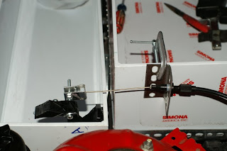
The first thing I built was swage assembly where the throttle cable terminates. It holds a plastic spacer that holds the cable in place in the assembly. The swage assembly is held in place on a screw that I've put through the pedal arm. As you can see, I've sawed the pedal it's self off.
The cable was originally passed through and was mounted to a metal plate. You can see on the right side, I've built something that approximates that piece. The cable goes though that piece of steel, and is held in place by a bushing. You can turn that piece behind the bushing to move it closer or further from the connection point at the end, essentially for fine adjustments to the throttle cable position. (Eventually the C clamp will give way to a permanent mount on the box.)
The cable has 46 mm of travel from when the pedal in the car is up to fully floored. I've measured and mounted it the assembly carefully so that it also has exactly 46 mm of travel. Of course with the fine adjustments I can make to the cable in, and a movable hard stop located under the pedal in the car, I should be able to get it exactly right.
I tested the pedal and it's a bit stiffer than I would have liked, but such is life.
Over the weekend I wrote down a list of everything left to do at this point. There are 43 items on the list, 14 of which are dependent on the batteries being here in the garage. Well I found out yesterday that the soonest they will arrive is the end of November. That means I have roughly 3 weeks to do the remaining 29 items. Today I knocked 3 off, so I'm down to 26. I'm sure that others tasks will be added to the list as things pop up, but overall, I'd say I'm making good progress.
Friday, November 6, 2009
Fitting Details
Over the past few days I've come to realize that it's time to solve some of the problems that have been nagging me for months. There was only one way to solve them, and that was through careful planning, measuring and fitting. Boring, maybe; necessary, absolutely.
There are three components to the high voltage lines that I need to find a home for. There's the rather large push button kill switch. If things go horribly wrong, or I need to work on the car and I want the battery pack disengaged, that switch will allow me to take care of that. There's the 500 amp shunt for the instrumentation. It allows the Link 10 meter to monitor the pack without "seeing" the full amperage, which would fry the meter. Last, there's the fuse. And that thing is big. It's about 5 inches long and the diameter of a half dollar coin.
I had originally thought that I'd put each of those in the trunk near the back battery box, but after thinking about it, I realized that would be kind of stupid. All 48 of the batteries will be wired in series, starting at one end (the trunk) and moving to the front. In order to put the disconnect and the shunt in the trunk, I'd have to run a line from the negative terminal up front all the way back to the trunk for those components, and then run it back up to the front again to the controller. A better answer was to find a place up front.
I put all the battery trays and boxes in place, just looking for extra space somewhere around them. While doing that, I remembered that the way the new batteries will be laid out in the two small trays means there will be some space left over on the ends. It had never occurred to me that I might use that space in a tray for something other than a battery, but when I got to looking, I realized it would work just fine for the disconnect switch. Some quick fabrication, and I had it mounted. I still need to locate the shunt, but it's small. The fuse can still go in back because it only needs to be inline on the positive side.
 Can't miss that sucker!
On top of that, I found a location for the throttle pedal. The pedal is meant to be a direct replacement for the pedal that came with the car. But Trust me, if you saw the new pedal and the car's pedal assembly, you'd say the same thing I did, "Oh, there's no way..." Well, not without taking the whole assembly out of the car, cutting it up, welding new bits to it at odd angles and refitting it. Well, I realized that extra space in the second box may work out for me, and it did.

Obviously it's not mounted up yet, just propped into place. But you can see that it fits nicely in the space, and you can see the car's existing throttle cable just peeking over the corner of the tray is in perfect alignment to mount to the pedal. Basically what I'll do is lop off the pedal part, and mount a swivel harness to the remaining stump. When I press on the car's accelerator pedal, it will pull that cable and activate the new throttle assembly. How great is that!? Well, it excited me.
Wednesday, November 4, 2009
Wiring Up Part II
One of the things that left with the engine and the ECU was the connector that goes to the reversing switch on the transmission. The switch is still in the transmission, but there's no way to connect it up to the car. I had to find the line back in the trunk that ran to the reversing lights. It turned out to be easier than I'd hoped. Once I isolated which wire it was, I cut it as far back as I could in the wire loom that runs into the trunk and spliced it to a new wire that runs to the switch. On the other side of the switch, I have a wire running to a power source. Problem solved.
I also ran a 12 volt line back to the battery box in the trunk. and one from the fan that will vent the battery box in the trunk. Those two lines will be connected together with a temperature switch in between them. When the temperature hits 122, the fan will kick on and force fresh air into the box.
I added a new relay in the electrics bay. This relay will work as a check for the heater. I'll hook it up to the car's ventilation fan, so that when the fan is turned on, it will power the new relay. That in turn, will power the switch for the heater in the cabin. If I turn on that switch, it will power the big contactor/relay I pointed out a couple days ago, and that will turn on the heater. Why so complex, you ask? This will ensure that the heater can not be turned on unless the fan is already on. I really want to avoid setting the car on fire.
Tuesday, November 3, 2009
Wiring Up Part I
Today was the day to start running power to all the auxiliary electrical equipment. It went fairly well, and I got quite a lot done. Here's a quick list of the bits that are ready.
1. Pedestrian horn with momentary switch (press it, it's on; let it go, it's off).
2. Motor cooling blower.
3. Vacuum pump for the brakes.
4. Water pump to cool the Zilla Controller.
5. Fuse box for all components switched on by ignition switch.
6. High power lines to the power steering pump.
I still need to install the proximity switch for the power steering pump as well as wire the off delay relay, but the schematics for that relay are a bit over my head. I'm going to have to ask someone to help me decode it.
So that was all the easy stuff. Onto more difficult things tomorrow.
Monday, November 2, 2009
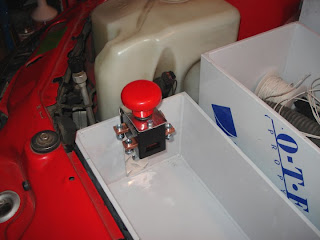
Electrical Work and a Horn
I mounted the lower electrics tray today and began wiring up some of the components. Unfortunately as soon as I'd begin working on one component, I'd realize I needed a connector I didn't have, so I'd move to another only to find the same thing. Instead, I did what I could and made a list of connectors that I need.
 Those of you who have been paying close attention will notice that the component on the upper right (in this picture) is different from the one I was planning to use, pictured in an earlier post. That is the position I set aside for the relay for the heating element. The original relay is really only designed for 10 amps at 150 VDC. Well, with the change in batteries, there was a change in voltage as well. The new pack will have as much as 165 VDC, and the heater can draw nearly 20 amps. I mean I want the heater to warm the car, but not by setting it on fire. So, I needed something else. The cylinder like component you see there is a high voltage contactor. It's really kind of overkill for the application, but it will work. I'll be using a similar one to actually turn the car on and off. I originally bought it to use as the relay for the DC motor I was going to use to power the A/C compressor. But when that motor didn't fit, and I had to redesign things, that contactor was going to go unused. Well, not anymore! I should get heat, with no fires. Always a good thing in a car.

I also mounted up the pedestrian horn today. Since the car will likely sneak through parking lots and streets in a virtual stealth mode, there's always the possibility that I'll need to make someone aware of my presence. I actually borrowed this idea from GM and the original EV1 car. The pedestrian horn is on a separate switch, and is about half as loud. There's a little screw on the back of the horn that lets you set the volume. No need to scare someone out of their skin with a blast from the regular horn.
 Those of you who have been paying close attention will notice that the component on the upper right (in this picture) is different from the one I was planning to use, pictured in an earlier post. That is the position I set aside for the relay for the heating element. The original relay is really only designed for 10 amps at 150 VDC. Well, with the change in batteries, there was a change in voltage as well. The new pack will have as much as 165 VDC, and the heater can draw nearly 20 amps. I mean I want the heater to warm the car, but not by setting it on fire. So, I needed something else. The cylinder like component you see there is a high voltage contactor. It's really kind of overkill for the application, but it will work. I'll be using a similar one to actually turn the car on and off. I originally bought it to use as the relay for the DC motor I was going to use to power the A/C compressor. But when that motor didn't fit, and I had to redesign things, that contactor was going to go unused. Well, not anymore! I should get heat, with no fires. Always a good thing in a car.
I also mounted up the pedestrian horn today. Since the car will likely sneak through parking lots and streets in a virtual stealth mode, there's always the possibility that I'll need to make someone aware of my presence. I actually borrowed this idea from GM and the original EV1 car. The pedestrian horn is on a separate switch, and is about half as loud. There's a little screw on the back of the horn that lets you set the volume. No need to scare someone out of their skin with a blast from the regular horn.
Subscribe to:
Posts (Atom)